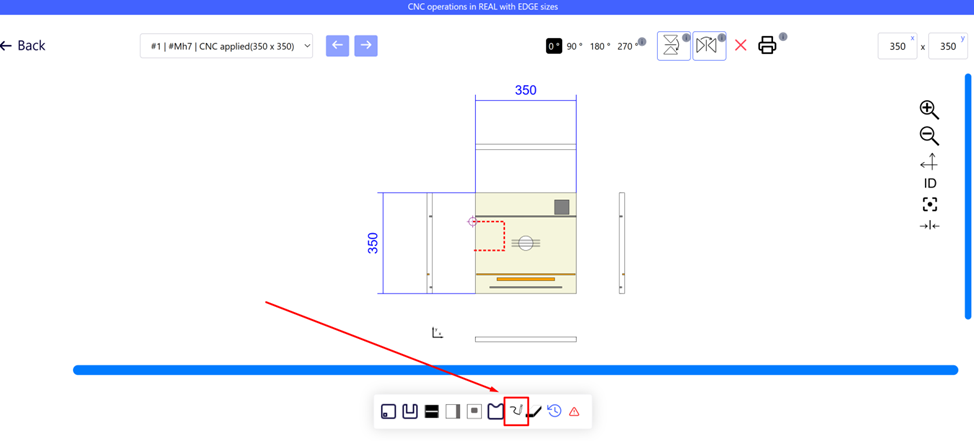
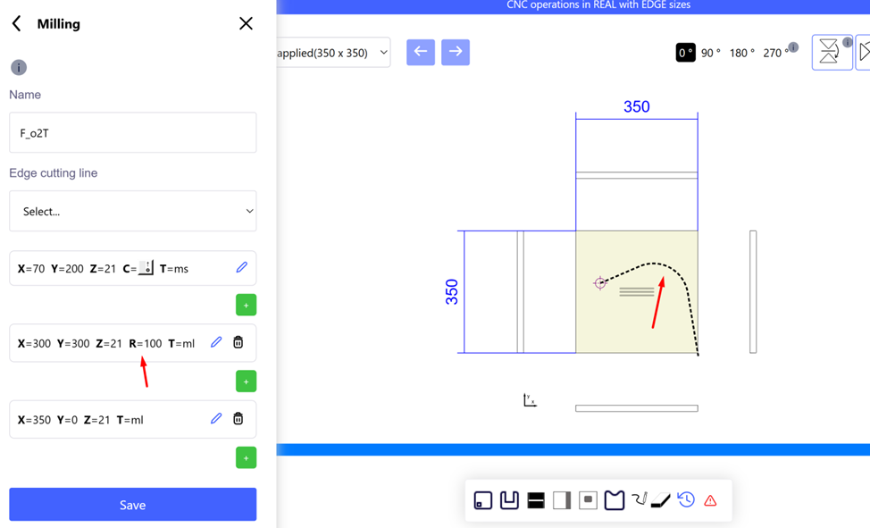
In the iFurn.Pro part editor you can create or change a milling contour:
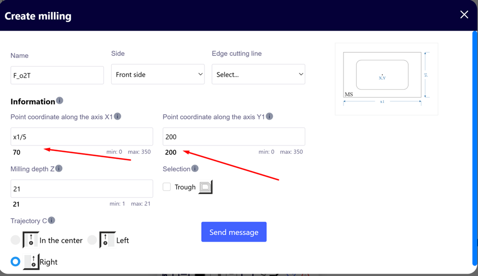
- Select points manually (x, y, z coordinates – numbers or formulas).
- Import of finished milling from the same project.
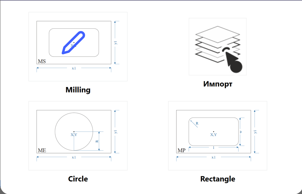
- Make a circle or rectangle.
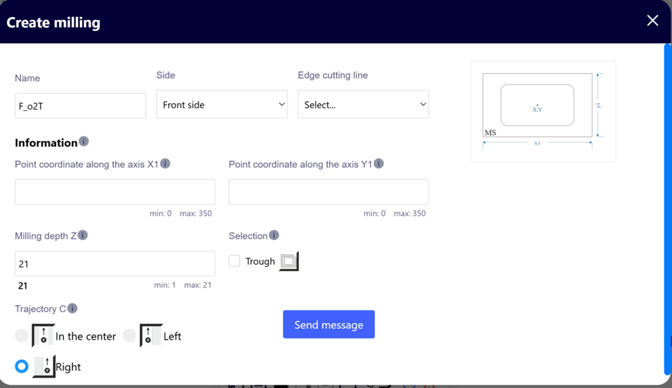
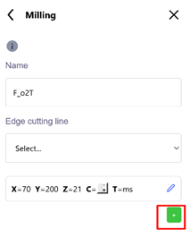
When creating a milling cut, the first cutter entry point is entered.
To create a pocket, check the “notch” box. Specify the position of the cutter relative to the cutting path, the need for edging and the name of the milling.
 |
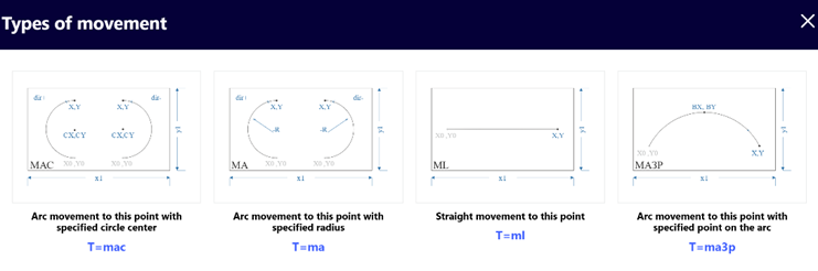 |
The following points:
- Straight line – set x, y, z from the previous point.

- Circle—select a center, radius, or point on an arc, specify the direction and end.
- The connection of straight lines can be rounded.
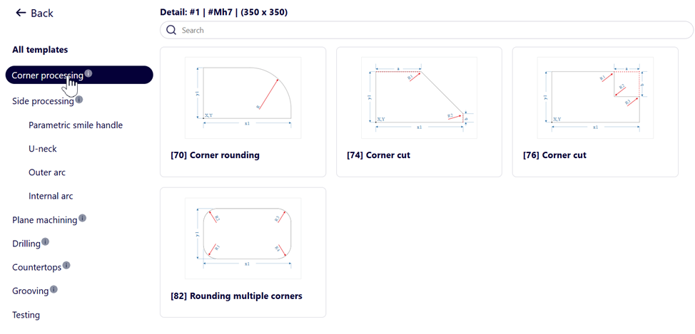
Manual configuration requires skills; it is better to use templates (cover 90% of tasks).
Milling templates cover 90% of the required processing needs:
Automation iFurn.Pro
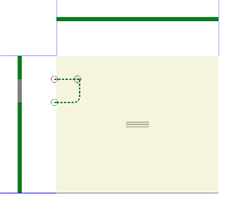
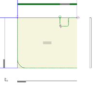
The entry/exit of the cutter is adjusted automatically.
2 examples below are incorrect
iFurn . pro automatically creates or adjusts cutter entry and exit.
 |
 |
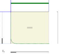
Adjusting the milling path
 |
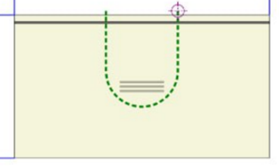 |
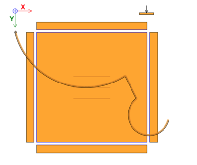
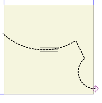
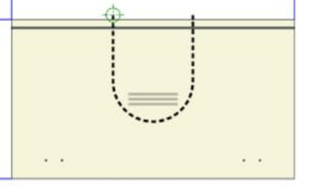
Which direction the cutter is rotating (left or right) is important when the cutter enters the part and moves inside the part. Example: Both parts are correct, but if you only have a right-hand cutter on the machine, the first part will be poorly made. When importing into iFurn . pro all motion trajectories change to suit the right cutter. |
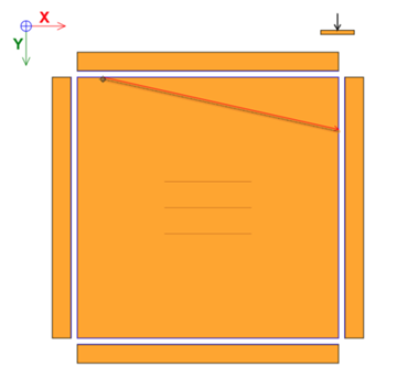
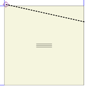
When exporting programs to machines, iFurn . pro rebuilds the trajectory to the cutter that is selected for milling. If the main cutter is the left cutter, when exporting, the system will first change the path, then export the programs.
In each machine you specify a set of cutters. Which trajectory will be unloaded onto the machine depends on the main cutter.
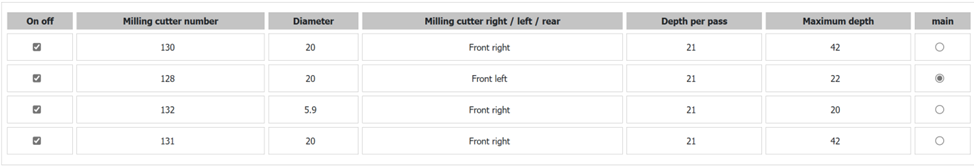
Cutter selection
The cutter is selected according to the maximum size, but not larger than the internal radius in the milling (for example, a radius of 20 mm - cutter 130, radius 8 mm - cutter 132).
Cleaning Illegal Milling Cuts
If the cutter is not suitable in radius or depth, the milling is deleted during export (information in the log file). Also in the CRM, the system will show which treatments were deleted for which of the machines.
Milling depth
You specify for each cutter the maximum milling depth and the milling depth in 1 pass. Assuming a milling depth of 35 mm, the maximum milling depth of a 42 mm cutter in one pass is 16 mm. The system will automatically unload 3 milling cuts (16mm, 32mm, 35mm).
Main cutter diameter

Affects import and processing. If the radius is less than the diameter + 1 mm, the curve will become straight. Set the minimum diameter of available cutters.
Cutter name
Enter only numbers in the admin panel for compatibility with machines. A disabled cutter is switched off from applications.
Trimming
Often the part is edged first and then milled. In this case, when leaving the part, the cutter tears out the edge and the part becomes of poor quality.
 |
iFurn . pro automatically adds edge trimming before main routing. If routing is done with the right cutter, the system will trim the edge with the left cutter. The same rules apply to the left cutter, if it is the main one. Then trimming can be done with a right-hand cutter. When trimming, the cutter enters the part by 3mm, which guarantees a clean exit of the main cutter. If the machine has one cutter, the system will add another milling program with trimming on the back side of the part. |
Cleaning right angles
 |
At a right angle, a large cutter (for example, 20 mm) leaves a radius (10 mm). If the cutter is smaller (for example, 4 mm) the angle is refined by an additional milling program to a radius of 2 mm. When applying this operation iFurn . pro automatically adds the service “ J17 Refinement of 90 degree angles with a smaller cutter ” to the calculation. |
Milling cut edge
 |
 |
iFurn . pro allows you to specify the edges of both sides and separately the edges of the milling cut. - if the edges of the cut and the edges of the side coincide, then the system will remove duplication in the calculation. services and materials. - sawing programs will be adjusted taking into account the influence of the edge of the milling cut on the sides of the part. - in the drawing of the part you can see which parts of the side will be fixed and which parts will be cut off during milling. If the side is edged, the edge color will indicate the edged part. The part being cut is shown in gray. |
Labels
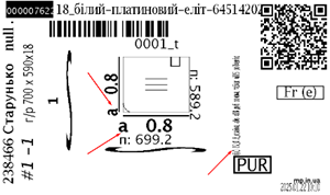 |
When edging a milling cut and its impact on the sides of the part, the system displays this information on the label. The operator will see which sides are affected by the edge of the milling cut. The output is made in both types of labels ( iFurn . pro / Giblab ). |
Notches
When exporting recesses, the trajectory “to the right of the cutter” was used.
The tool has been automatically selected. For example, if the smaller side of the recess is 22 mm, the recess will be made with a cutter with a diameter of 20 mm. If the machine has a smaller cutter diameter, the system will add a second contour to clean the corners (for a rectangle). In some cases, notches are discharged without being converted into linear cuts (depending on the machine). In this case, the operation is completed faster. In any case, a smaller cut with a cutter is added regardless of the unloading format.
When checking cutout restrictions, the system now checks not the main diameter of the cutter, but rather all available cutters. An error occurs if the recess cannot be made with any cutter.
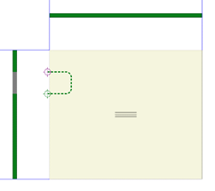
Post-cutting and edging programs
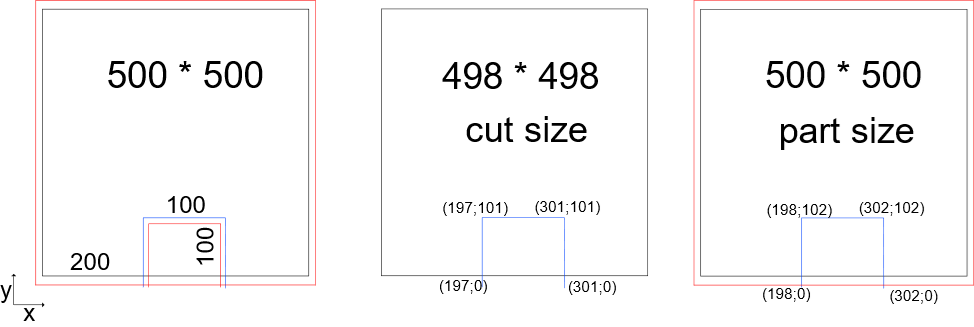
The part can have 2 different sizes:
- size after alert center (cut)
- Size after edge( part )
When edging milling cuts, the edges are usually first made on a jointing machine, then the edge is routed and glued to the curved areas.
In the example, the cutout should be 100*100mm. The cutout is edged. The trajectory towards the edge is different from the trajectory after the edge.
iFurn . pro automatically calculates the required trajectories.
Uploading programs to the machine contains two program options. The machine operator simply selects which program to use. If the part arrived already fixed, then the program for the overall size ( part_size ) is used , if the part arrived at the edge, the program for saw dimensions ( cut_size ) is used .
All contours are corrected, including arcs.